Week 10
Single-phase Full Bridge Inverter

(a) Circuit diagram.
Functions:
- A voltage source inverter generates an AC output voltage from a DC input with the adjustments of turning ON and OFF to produce a voltage of +Vdc, -Vdc, or zero.
- It consists of 4 thyristors and 4 flyback diodes.
Working Principle:

(b) Current flows in circuit during 1st half-cycle.

(c) Current flows in circuit during 2nd half-cycle.

(d) Circuit waveform for both half-cycle.
- A pair of diagonal thyristors is triggered in each half-cycle.
- During 1st half-cycle, the thyristors (T1 & T2) are ON while others are OFF and the load voltage is equal to the source voltage with positive polarity (Vo=+Vs).
- During the next half-cycle, the thyristors (T3 & T4) are ON while others are OFF and the load voltage is equal to the negative polarity of the source voltage (Vo=-Vs).
- Diodes (D1 to D4) purpose is to ensure the output voltage and current are always in phase if the loads are not purely resistive.
- The diodes are connected anti-parallel with the thyristors to allow the current flows when the main thyristors are OFF.
- These diodes will feedback on the energy to the DC source.
Advantages:
- The output power is 4 times the half-bridge inverter.
- Provides a full-cycle output (continuous).
Disadvantages:
- Requires two-wire DC source.
- Costlier due to more thyristors and diodes used compared to the half-bridge inverter.
Pulse Width Modulation (PWM)
(e) PWM block diagram.
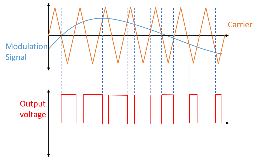
(f) PWM waveform.
Functions:
- A method to control semiconductor devices that generates analog signals from digital devices such as microcontrollers.
- The signal will produce pulses in forms of square waves.
- This modulating technique is to reduce the average electrical input power into discrete parts.
Working Principle:
- It is generated by using a comparator.
- There are two inputs of the comparator where sawtooth wave will be at the positive input while modulating signal will be at the negative input.
- The comparator will compare both of these signals to generate a PWM signal which is a modulated pulse signal.
- If the sawtooth signal is more than the modulating signal, output signal will be HIGH.
- If modulating signal is more than the sawtooth signal, output signal will be LOW.
- The pulses of the output signal are determined by the value of the magnitudes.
Important Parameters:
1. Duty Cycle
- PWM signals switches ON and OFF for a certain time.
- The duty cycle is the time percentage when the signal is ON.
- The average value of the voltage is depended on the duty cycle that can be varied by controlling the width of the signal when it is ON.
2. Frequency
- The frequency determines the speed of a PWM completes a period.
Advantages:
- Accurate and fast-response.
- Provides high input power factor.
Disadvantages:
- Switching losses is high when the frequency is high.
- It induces Radio Frequency Interference (RFI).
Week 11
UPS Runtime Period
- UPS runtime is the time period a UPS can provide backup supply to the critical loads when the utility power supply fails.
- The calculation of the UPS runtime is to multiply the UPS battery capacity by the UPS input voltage and then divide the sum by the total watts of the critical loads. (UPS runtime (hour) = Battery capacity (Ah) x Input voltage (V) / Total load (watts)).
Improve UPS Runtime:
- Decrease loads to gain more runtime period.
- Ensure components used have high efficiency to reduce power losses and more runtime period.
- Provide the correct charge settings for the battery to avoid overcharging.
Week 12
Preliminary Result: Component design simulation on Single-Phase Full-Wave Controlled Rectifier.
(a) Circuit diagram of single phase full wave controlled rectifier in MATLAB Simulink.
(b) Waveform of input voltage and output voltage and current.
Comments
MOHD FADLI BIN RAHMAT
25 January 2023, 2:48 PM
Great effort