Week 6
UPS System Classifications:
- Static UPS System
- Rotary UPS System
- Hybrid Static/Rotary UPS System
1. Static UPS System
This classification of the UPS system is the most common used UPS system as it can be used for broad variety of applications from low to medium to high power systems. The benefits of static UPS system is due to its high efficiency and reliability as well as low THD. However, it has low tolerance with unbalanced loads that cause it to behave poorly. The system is very low cost effective for it be a system with high reliability. The configurations of the static UPS system includes on-line, off-line, and line-interactive.
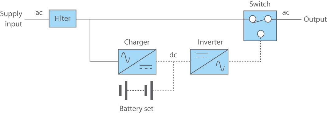
(a) On-line (Double-conversion) UPS System

(a) UPS system with double-conversion technique block diagram.
This configuration type of a static UPS system consist of four main components which are rectifier, a battery set, inverter, and static bypass switch. The main AC power supply will be inputted into the rectifier to convert it into DC power supply which will be used to charge the battery set. The power rating must meet 100% of the power demanded by the load and power demanded to charge the batteries. This is to ensure the emergency supply from the system is enough to supply the load when the utility power supply fails. The time duration for the UPS system to provide the backup supply is very much depended to the applications. The inverter too must meet 100% of the power demanded by the load as it not only needed to supply the load during backup time but also in normal mode of operation. This system is always ON which causing it have zero switching time when transferring from normal mode to store energy mode. The main advantage of double-conversion UPS system is it has a static bypass switch that is used to easily switch the load to the main AC power supply whenever there is fault happens within the system. Nevertheless, the main AC power supply and the load voltage must be in phase with the use of locked-phase control loop system for the static bypass switch to work.
(i) Normal Mode
When the system is in this mode operation of the double-conversion UPS, the main AC power supply is continuously supplied to the load through the rectifier and inverter which causing it to have power conditioning. The flow starts with the main AC power supply inputted to the rectifier and the output DC power is supplied to the batteries to be charged. Then, the load will be supplied after the DC power of the batteries inputted to the inverter to be converted to AC supply. In order for the system to run smoothly, the power rating for both rectifier and inverter must be fully met to the load's demand which causing it to be a non-cost effective topology of this UPS system.
(ii) Stored-energy Mode
This mode operation will only operate when there is a utility power supply failure where the load will still have power to functioned from the batteries via the inverter. The duration of this mode is depended on preset UPS backup time or until the main AC power supply is back. A phase-locked loop (PLL) is used to make the load voltage and the input voltage in phase to return the UPS operating mode to normal mode.
(iii) Bypass Mode
When the UPS system experienced failures, this mode will be operated but it is required to ensure the output frequency of the system and the frequency of the main AC power supply are the same as it is important for power transferring.
(b) Off-line (Standby) UPS System
(b) Offline UPS system block diagram.
This system consists of components like a rectifier, a battery bank, inverter, a static switch. a filter at the output to improve quality of the output AC voltage from the inverter. The static switch is ON during normal mode of operation when the main supply AC power is available which it will directly supplied the AC power to the load with no power conditioning. The power rating of the rectifier does not have to meet 100% power demanded by the load to charge the batteries. However, the inverter must meet 100% of the power demanded by the load and will stay standby in normal mode. It will turned ON when there is blackout happens where the load will be supplied by the a set of batteries through the inverter until the main AC power supply is available again. Since the inverter is not ON during normal mode operation, therefore the main AC power supply does not always do correction on the power factor but it does functioned as an active filter to reduce harmonics of the supply current.
(c) Line-interactive System

(c) Line-interactive UPS system block diagram.
The components included in this system are a static switch, a series inductor, a bidirectional converter, and a battery set. This system can be functioned in both operations, on-line and off-line UPS system operations. The series inductor is not required when operating in off-line UPS mode. The system is usually operated in on-line mode to improve power factor and regulate output voltage for the load. The main AC power supply is provided directly to the loads while the inverter is connected in parallel with the the load. Aside from charging the batteries, the inverter is used to regulate the output voltage and to provide an almost unity power factor by supplying a required amount of reactive power for undervoltage condition and consuming the reactive power when overvoltage occurs. When blackout happens, the static switch is OFF where the load will start to be supplied from the batteries via the inverter with its rated power is fully met with the load's demand.
The benefits and drawbacks of the on-line (double-conversion) UPS system:
1. Benefits:
- Wide tolerance to the input voltage variation
- Precise regulation of output voltage
- Zero transfer time when transitioning between modes of operation
- Possible to change or regulate output frequency.
2. Drawbacks:
- Low power factor - The system cannot fully utilize the utility network and local installation.
- High total harmonics distortion (THD) at the input supply - It may not be cost effective to add an extra power correction factor (PFC) to reduce the distortion at the input.
- Low efficiency - This is due to the double conversion of the system which causing it to experience high power loss.
2. Rotary UPS system
A typical rotary UPS consist of an AC motor, a DC machine, an AC generator, and a battery bank. The electrical machines are mechanically coupled and this system operates in two different modes which are normal mode and standby mode, During normal mode, the main AC power supply is provided to the AC motor to drive the DC machine which will also drive the AC generator to supply the load. During standby mode, the battery bank provide electrical supplies to the DC machine that drives the AC generator to supply the load.
Rotary UPS is much more reliable than the static UPS, but it requires more maintenance and is larger in size and weight. It can worked well for high-power applications as it has higher capability (300 - 600%) on transient overload for rapid fault clearing compared to static UPS (150%). The other advantages would be its good performance with unbalanced loads due to the its low output impedance. It has a low EMI and a very low input THD with 3% or lower that comes in addition to its higher efficiency of 85% or above.
3. Hybrid Static/Rotary UPS
This UPS system is a combination of both static and rotary UPS systems. This system has low output impedance, high reliability, excellent frequency stability, and low maintenance cost due to the system has no mechanical commutator. The hybrid system consist of a bidirectional AC/DC converter, an AC motor, an AC generator, a battery bank, and a static switch.
During normal mode, the AC motor is supplied by the main AC power supply to drive the AC generator which will supply to the load. The bidirectional AC/DC converter behaves as a rectifier to convert the AC power to DC power for it to charge the battery bank. During stored energy mode, the bidirectional converter behaves as an inverter that supply the AC generator from the batteries via the AC motor. When there is a fault condition within the UPS system, the static bypass switch is ON and the load will be supplied directly from the main AC power supply but the transition is not transient-free due to the main supply and the output voltage are not sync.
The system's AC generator is started by the utility power supply to avoid starting overcurrent for the inverter to be rated in normal mode. Once the AC generator is ON, the main AC power supply will be cut off and the power from the generator is supplied to the inverter.
Week 7
There are four main components of a conventional UPS system:
1. Rectifier
- Main function: To convert input AC power to DC power
- It is also used as a charger to charge the battery set in the UPS system
2. Battery Set
- The battery set is charged with the DC power from the rectifier.
- The charged battery set will be used as a backup supply to provide emergency power to the critical loads when the utility power supply fails.
- The up system can have more than one battery depending on the required loads to be supplied during blackout.
- The batteries are connected in series, thus the whole set of battery will be failed if one of them fails.
3. Inverter
- Main function: To convert DC power output from the rectifier or battery set to AC power.
- The reason to convert the power to AC is due to the critical loads are in AC, therefore it is a required process to ensure the system can provide emergency supply to the critical load.
- A filter is also a part of the inverter which functions to smoothen the sinewave from spikes, surges, and noises.
- The transformer is used to step-up the AC output voltage from the inverter to be transferred to the critical loads as well as to provide electrical isolation and load protection.
4. Static Bypass Switch
- The switch purpose is to bypass the normal UPS operation if there is any fault condition happens within the system.
- It will automatically connects the load to the main supply with it bypassing the rectifier, inverter, battery set.
- The main supply that provides the load is not filtered, hence an external maintenance bypass switch is used to powered down the UPS manually for maintenance while the loads are powered directly from the main supply.
- The external maintenance bypass switch is a circuit breaker or rotary switch-based that uses to isolate the UPS system for maintenance or unit replacement without any disturbance to the load.
- Once the fault has been cleared, the switch will instantly transfers the load back to the UPS.
Additional components in my designed UPS system:
1. Buck Converter
- It is a type of a DC-DC converter which also known as a step-down voltage regulators where the DC output voltage must be lower than the DC input voltage.
- This converter will be placed between the rectifier and battery set which it will used to step-down the DC voltage from the rectifier to charge the batteries.
2. PID Controller
- Proportional integral derivative (PID) controller is an instrument used in the industrial control applications to regulate process variables.
- It uses a control loop feedback mechanism to keep the actual output of a process as close to the target setpoint output as possible.
- This controller will be integrated together with the buck converter to regulate a close value of a DC voltage to be charged into the batteries.
Week 8
Single-phase Full Wave Rectifier

(a) Circuit diagram.
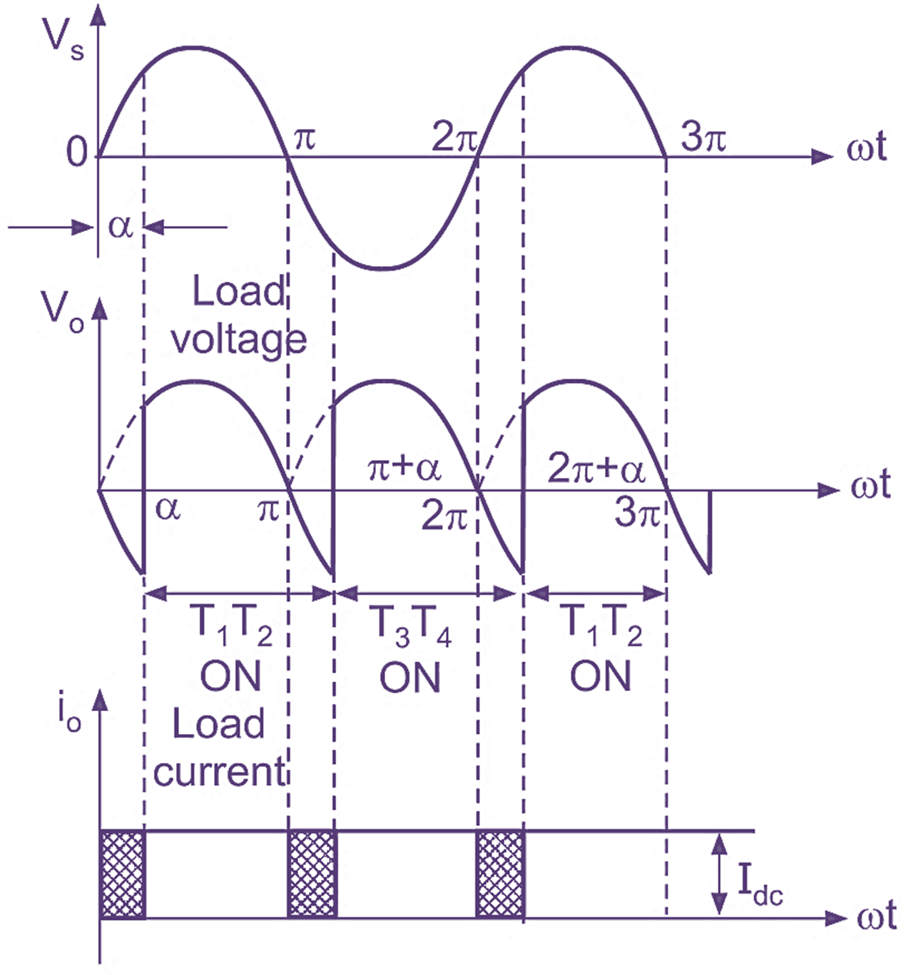
(b) Input and output voltage and current waveform.
Functions:
- To convert Alternating Current (AC) supply to Direct Current (DC).
- It uses thyristors which is a semi-controlled rectifier (SCR) as the devices.
- These thyristors are controlled by adjusting the firing angle.
- The devices works in pairs where on each cycle (positive and negative cycles), 2 thyristors (T1 & T2) will ON while other 2 (T3 & T4) will be OFF and alternately.
- In positive half-cycle, the output voltage and current is equal to the voltage and current source (Vo=Vs, Io=Is).
- In negative half-cycle, the output current is the opposite of the source current (Is=Io).
- The thyristors are constantly switched alternately in pairs to maintain the average DC output voltage.
Advantages:
- It is more efficient than the half-wave rectifier due to both half-cycles of the input sinewave can provide a higher average DC output voltage.
- The maximum efficiency of the full-wave rectifier is 81.2% which is twice the efficiency of the half-wave rectifier (40.6%).
- The current flows through the load is continuous.
- Ripple factor of the full-wave rectifier is lower (0.482) compared to half-wave rectifier (1.21).
Disadvantages:
- It requires more diodes or thyristors which is costlier.
Week 9
Buck Converter

(a) Buck converter when switch is CLOSED (ON) and OPENED (OFF).
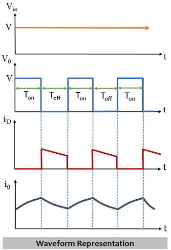
(b) Buck converter waveform during ON and OFF states.
Functions:
- A converter device to step-down the DC voltage where the output voltage must be lower than the input voltage.
- It uses power electronics switch such as MOSFET, IGBT, BJT that will be controlled by the PWM signal.
- The devices include in this converter are a switching device, a diode, an inductor, and a capacitor as well as a source.
Working Principle:
1. Switch CLOSED (ON)
- Current flows to the capacitor to charge it.
- When the current flows, the inductor limits it which causing the voltage across the capacitor to rise instantly.
2. Switch OPEN (OFF)
- The inductor creates voltage across the circuit to the capacitor to be charged and to power the load through the diode.
- This functions to maintain the output current throughout the switching cycles.
*Both of these steps worked continuously and repeatedly to result a continuous output.
Design Procedures:
1. Calculate duty cycle to obtain a required output voltage.
2. Select a particular switching frequency, f and device:
- Frequency higher than 20Hz is preferable to avoid acoustic noise.
- Higher switching frequency, fs will result in smaller L and C (higher losses, reduce efficiency, larger heat sink).
- Possible devices: MOSFET, IGBT, BJT. (MOSFET can reach MHz range).
3. Calculate minimum inductance, Lmin to choose a higher value of inductance, L (L>>10Lmin).
4. Calculate capacitance, C for ripple factor requirement:
- Capacitor ratings must able to withstand peak output voltage.
- It also must able to carry the required RMS current.
Proportional-Integral-Derivative (PID) Controller

(a) PID controller block diagram.
Functions:
- It is a controlled closed-loop feedback controller to deliver output control at desired levels.
- The P, I, and D are the three controllers that combined to produce a control signal.
- It is processed by the microprocessors.
- It can control variables processes such as pressure, temperature, speed, and flow for industrial applications.
- The system will evaluate the feedback variable using a fixed point to generate an error signal which to alter the system output.
- This step will continue until the error reaches zero.
Working Principle:
1. Proportional (P) controller
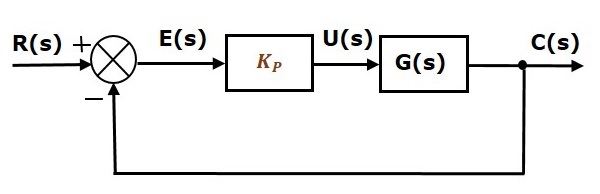
(b) P-controller block diagram.
- Gives an output that is proportional to the system error (controller output = error value).
- It compares the actual value of a system with the desired fixed value.
- The resulting error will be multiplied with the proportional constant desired value to get the output.
- This controller requires manual reset due to it never reaches steady-state condition when used alone.
- The speed of the response works proportional to the constant Kc (Increase Kc, increase speed).
2. Integral (I) controller
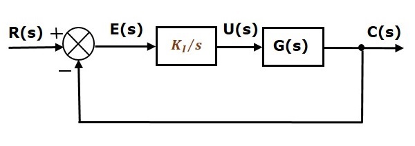
(c) I-controller block diagram.
- This controller is to provide elimination of the steady-state error.
- It will integrate the error over a time period until it reaches zero and hold it to the final control device.
- It decreases the output when the error is negative that limits the speed of the response and affects the stability of the system.
- The integral gain, Ki can increase the speed of the response by decreasing it that will also resulting the steady-state to be decreased as well.
3. Differential (D) controller
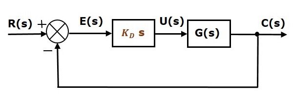
(d) D-controller block diagram.
- This controller is specialised to predict the future behaviour of the error.
- The output is depended to the rate of change of error with respect to time that multiplies with a derivative constant, Kd which increase the system response.
- The settling time is decreased which improves the stability of the system by compensating the phase lag.
- The increment of the derivative gain will increase the speed of the response.
Tuning Methods:
1. Trial & Error Method:
- The simplest method of PID controller tuning.
- The controller can be tune while the system or controller is working.
- Set the Ki and Kd values to zero and increase Kp until the system reaches oscillating behaviour.
- Once it oscillates, adjust Ki to stop the oscillations.
- Adjust Kd to get fast response.
2. Process Reaction Curve Technique:
- This method is an open-loop tuning technique.
- It response when a step input is applied to the system.
- Manually apply some control output to the system and record the response curve.
- Calculate the slope, falling and rising time of the curve.
- Substitute the calculated values in P, I, and D equations to get the gain values of the PID terms.
3. Zeigler-Nichols Method:
- This technique provides closed-loop method (continuous cycling method & damped oscillation method) for tuning the PID controller.
- Set Kp to a particular value while Ki and Kd remain zero.
- Increase Kp until the system oscillates at a constant amplitude.
- The system will produce 2 gains (ultimate gain, Ku and ultimate period, Pc).
- Insert the values of P, I, and D into the Zeigler-Nichols table depending on which PID controller used (P, PI, or PID).
Comments
MOHD FADLI BIN RAHMAT
25 January 2023, 2:47 PM
good effort