Reflection
I gained a lot of knowledge these four months studying digital logic. In class, we not only read from textbooks, but we get to do hands-on projects. The hands-on projects such as lab sessions allowed me to know more about electronics and how to apply them in the circuit. Furthermore, I learnt numbering system, logic gates, Boolean algebra, flip-flop, PLDs and much more. I get to know that analog computation is very costly in terms of power and design complexity. The analog signals are also very sensitive to errors and noise. If we can convert information into numbers rather than continuous time signals, it is far easier to process and store the data.
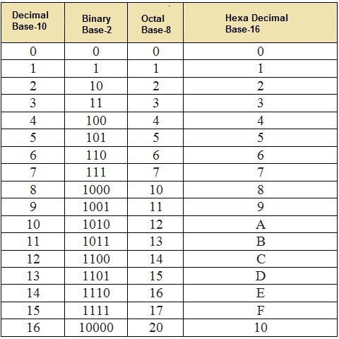
Modern integrated circuits, particularly the CMOS technologies that dominate the world today, have two primary reference voltage which are GROUND and SUPPLY. Since the CMOS transistors make great switches, it is easy to create circuits that produce signals at those two voltages (Ground & Supply). Binary (base 2) number format lends itself to representation in this environment are high & low voltage in a modern CMOS process. So, essentially all digital chips today use binary number systems to process data. These digital signals are extremely robust to noise and such. The signal only has to be near HIGH or LOW. There isn’t any ANALOG ‘detail’ to the signal, only a STATE. This is far more robust and this is why modern digital computers use BINARY to do all of the processing.
All in all, Digital Logic is a very fun course to learn. Many thanks to Dr Zuriahati who has always been patient during lectures and very supporting, Dr has really made the class more interesting.
MINI PROJECT - PHOTOCOPYING (XEROX) MACHINE
-
Download Lab 4 Report.docx.2
Lab 4 Report.docx.2 Details
- Monday, 30 December 2019 [2.1MB]
Deeds Simulator
-
Download Fig_Lab 2 (Circuit i).png
Fig_Lab 2 (Circuit i).png Details
- Monday, 30 December 2019 [2.6KB] -
Download Fig_Lab 2 (Circuit ii).png
Fig_Lab 2 (Circuit ii).png Details
- Monday, 30 December 2019 [3.8KB] -
Download Fig_Lab 2 (circuit iii) Dual-Symbol v2.png
Fig_Lab 2 (circuit iii) Dual-Symbol v2.png Details
- Monday, 30 December 2019 [5.9KB] -
Download Fig_Lab 2 (circuit iii) Dual-Symbol.png
Fig_Lab 2 (circuit iii) Dual-Symbol.png Details
- Monday, 30 December 2019 [6.2KB] -
Download Fig_Lab 2 (circuit iii) NAND.png
Fig_Lab 2 (circuit iii) NAND.png Details
- Monday, 30 December 2019 [5.1KB] -
Download Fig_Lab 2 (circuit iii).png
Fig_Lab 2 (circuit iii).png Details
- Monday, 30 December 2019 [4.2KB] -
Download TimingDiagram_Lab 2 (circuit iii) Dual-Symbol_TestSequence1.png
TimingDiagram_Lab 2 (circuit iii) Dual-Symbol_TestSequence1.png Details
- Monday, 30 December 2019 [313.5KB] -
Download TimingDiagram_Lab 2 (circuit iii)_TestSequence1.png
TimingDiagram_Lab 2 (circuit iii)_TestSequence1.png Details
- Monday, 30 December 2019 [314KB]